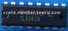
Product Summary
(1)The TL494 is a fixed–frequency pulse width modulation control circuit, incorporating the primary building blocks required for the control of a switching power supply. (See Figure 1.)An internal–linear sawtooth oscillator is frequency–programmable by two external components, RT and CT.; (2)Output pulse width modulation is accomplished by comparison of the positive sawtooth waveform across capacitor CT to either of two control signals. The NOR gates,which drive output transistors Q1 and Q2, are enabled only when the flip–flop clock–input line is in its low state. This happens only during that portion of time when the sawtooth voltage is greater than the control signals. Therefore, an increase in control–signal amplitude causes a corresponding linear decrease of output pulse width. (Refer to the Timing Diagram shown in Figure 2.); (3)The control signals are external inputs that can be fed into; the deadtime control, the error amplifier inputs, or the feedback input. The deadtime control comparator has an effective 120 mV input offset which limits the minimum output deadtime to approximately the first 4% of the sawtooth–cycle time. This would result in a maximum duty cycle on a given output of 96% with the output control grounded, and 48% with it connected to the reference line. Additional deadtime may be imposed on the output by setting the deadtime–control input to a fixed voltage, ranging between 0 V to 3.3 V.
Parametrics
(1)Power Supply Voltage :VCC 42V; (2)Collector Output Voltage VC1,VC2=42 V; (3)Collector Output Current(Each transistor) (Note 1):IC1,IC2=500mA; (4)Amplifier Input Voltage Range VIR:–0.3 to +42 V; (5)Power Dissipation @ TA≤45°C PD1000 mW; (6)Thermal Resistance,Junction–to–Ambient :RθJA 80°C/W; (7)Operating Junction Temperature TJ:125°C; (8)Storage Temperature Range Tstg:–55 to +125°C; (9)Operating Ambient Temperature Range, 0 to +70°C; (10)Derating Ambient Temperature TA:45°C
Features
(1)Complete Pulse Width Modulation Control Circuitry; (2)On–Chip Oscillator with Master or Slave Operation; (3)On–Chip Error Amplifiers; (4)On–Chip 5.0 V Reference; (5)Adjustable Deadtime Control; (6)Uncommitted Output Transistors Rated to 500 mA Source or Sink; (7)Output Control for Push–Pull or Single–Ended Operation; (8)Undervoltage Lockout
Diagrams
<IMG border=0 src="http://www.seekic.com/uploadfile/ic-mfg/20127274024553.jpg">
| Image | Part No | Mfg | Description |  |
Pricing (USD) |
Quantity | ||||||||||||
|---|---|---|---|---|---|---|---|---|---|---|---|---|---|---|---|---|---|---|
 |
 TL494CN |
 Texas Instruments |
 Voltage Mode PWM Controllers PWM Controller |
 Data Sheet |

|
|
||||||||||||
 |
 TL494CNE4 |
 Texas Instruments |
 Voltage Mode PWM Controllers Control Circuit |
 Data Sheet |

|
|
||||||||||||
 |
 TL494CNG |
 ON Semiconductor |
 Voltage Mode PWM Controllers 40kHz 200mA PWM w/48% Duty Cycle Max |
 Data Sheet |

|
|
||||||||||||
 |
 TL494CNSR |
 Texas Instruments |
 Voltage Mode PWM Controllers PWM Controller |
 Data Sheet |

|
|
||||||||||||
 |
 TL494CNSRG4 |
 Texas Instruments |
 Voltage Mode PWM Controllers Control Circuit |
 Data Sheet |

|
|
||||||||||||
 (Hong Kong)


